Project Title
Haptic Glove
Project Team Members
Kevin, Qiuxuan
Project Description
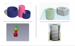
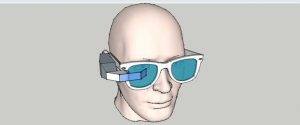
We hope to create a glove that can be used to interact with objects in virtual reality. Most of the virtual reality products now are focusing on visual experiences, such as “VR Goggle”. However, it loses touch sensations, such as the feeling of gravity and interaction force. Touch sensation plays a significant role in maximizing people’s experience. Therefore, we want to create a VR glove that uses special wires which are sensitive to temperature change (contract 3%-5% when exposed to heat or electrical current) to mimic the feeling of touching and pressure, to provide more realistic and engaging experience to users.
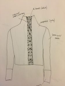
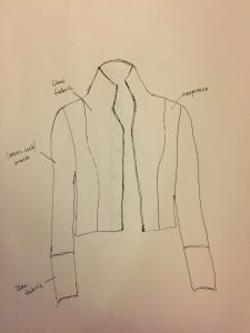
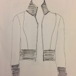
Sketches/Concept Art
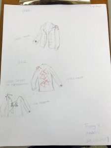
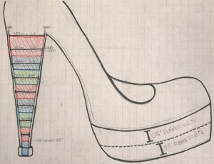
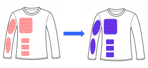
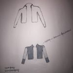
 Connection\mounting type will be a looped conventional wire, or perforated actuato
 r ribbon. Electrical connection will run in the gloves hemming for aesthetics and practicality.
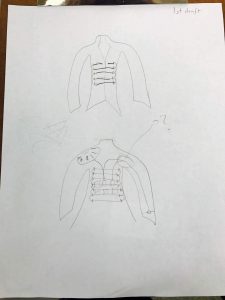
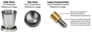
Securing the Actuator wire is the most critical step currently. The force that the wire generates, varying between gauge, may burst the mounting, may stretch the underlying fabric so that there is not haptic feedback. Maintaining a fixed location on the glove to engage a haptic response may require 3D printed “splints,” to counteract the lateral forces generated. Elastic tension may be required to run along the nail side of the finger to give the additional guarantee of proper response.
Consideration on mounting site must account for the ~5% contraction, so that tread does not break upon Actuator activation.
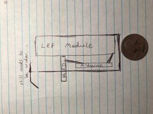
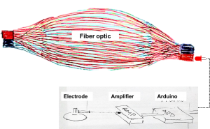
We will use Unity to develop the programming and connect the microcontrollers with gloves, letting the sensors to communicate with the computer.
Materials and Costs
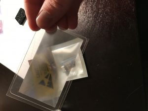
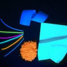
- FLEXINOL® Actuator Wire estimated cost: $10-20
- Microcontrollers and USB estimated cost: $40
- Glove estimated cost: $10
- Wires estimated cost: $10
- 3D-Printing Materials estimated cost: $20
Timeline
March 6: Have all necessary materials.
March 12: Finish (3D printing model) and wire design.
March 15: Test
Milestone 1 (March 16): The technology for the project is shown to work
Spring Break
March 30: Programming and combine it with the glove
April 5: Test on program
Milestone 2 (April 6): The technology has been shown to work in a wearable configuration
April 13: Prepare for demo
Milestone 3 (April 20): The technology and final wearable are fully integrated
Fallback Plans
Ideally, we hope to use FLEXINOL® Actuator wires to provide haptic feedback. However, if it is not applicable, we can use other wires and shape into alternate forms to provide better feedback. Or we can use the wire to pull a spring/coil or elastic band to provide feedback. Or we can use tiny rumble motors or electrodes.