1. Some Pics
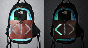
I use leather as the top layer, on it I carved the turning and stop signals. trying to keep the shapes simple and clean.
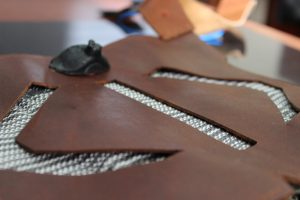
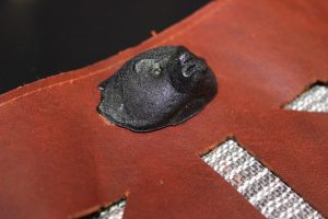
The stop light is activated via sensor which I disguised inside Bucky’s head. Bucky’s head was 3D printed with a hollow center to host the sensor.
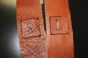
The turning signals were activated via pressure buttons located on the straps. Since the leather is thick and hard to press the buttons were initially cutout then attached to a thin rubber membrane, this way the lights could be activated without much effort.
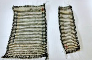
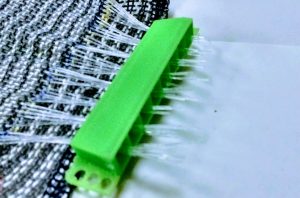
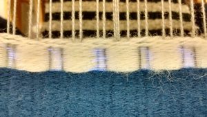
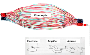
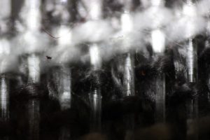
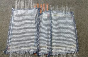
I used an optic fiber weaved fabric as the medium to display the light. For this I had to weave each optic fiber as well as channel it in to an LED.
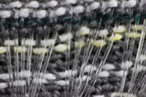
This is a close up of the fibers embedded in the fabric.
This is the final result, the wearable is attached to the back of my backpack, and once turned on at night it has a very effective light dispersion. It will definitely serve its purpose.
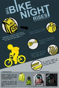
2. The Poster
3. What does it do
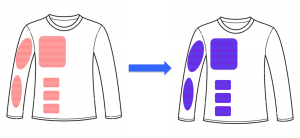
BIKE is sort of a vest for your backpack; its has 3 independent light displays that help you signal when driving you bike at night. The turning signs L-R are activated via wire and press button located at chest level in the straps of the backpack. The stop sign is activated via sensor embedded in bucky’s head.
It is composed of 3 layers:
a) the cover, in leather
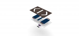
b) the fiber optic
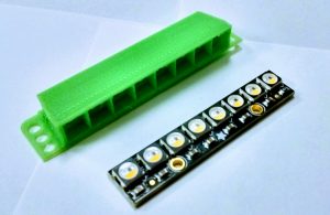
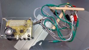
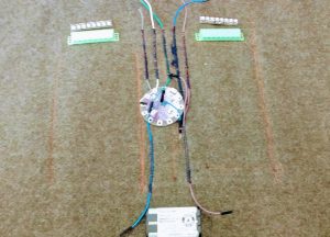
c) the electronics
4. What I think about the outcome
I think the purpose of BIKE is very straight forward, it has to light up when you tell it to , or when you stop on your bike. In that sense I’m pleased because it does what it’s supposed to. However I could have done a better job with the quality of the work; at the end the wiring and the assembly were not very clean.
5. Start vs. Finish
For starters I switched to my plan B at mid-semester, considering this my final prototype is very different to the goals I set to reach at the beginning of the semester.
In terms of the initial concept for BIKE, I initially though of it as a belt; but after some consideration I realized that a belt sized display wouldn’t have that much impact, and since I already had fiber optic pads with a certain size I decided to scale everything to fit them. The outcome is what you see in the pics.
6. Hurdles along the way
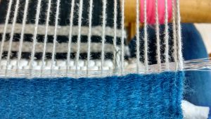
One of the most time consuming activities was the construction of the fiber optic pads. Concept wise it is very simple: the fibers need to be sanded a little so the light slips through and the tips have to be clean cut so the light enters without any restriction. But during the construction this prove to be quite cumbersome.
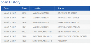
Another hurdle was the shipping of materials, and this was the main reason why I hat to switch to my plan B project. I could fine very cheap electronics in Amazon, but most of them come from China, and the leap time is more than one month (on average).
7. Whit more time…
I would purchased a new Lily-pad (my lily-pad broke down a couple days before the showcase) and I would have use the neopixels, in a more interactive way, maybe a blinking signal.