Sirena 3/28/17

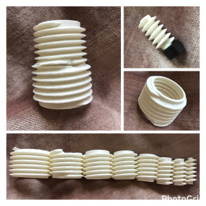
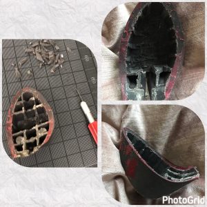
On Thursday Emma was figuring out how she could possibly 3D print part of the bracelet so all the tech won’t show or be felt when the bracelet is worn. Thought of using the 3D printer to print a sort of square box that the simblee and battery could sit in, which would allow the button to be pressed from the exterior wearer.


Planning to continue to work on the 3D printing concept this week using TinkerCAD.


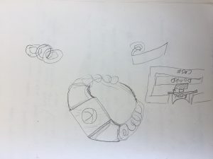
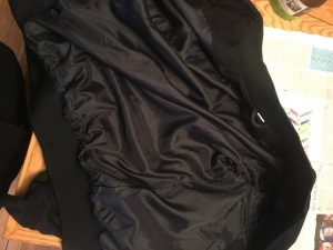
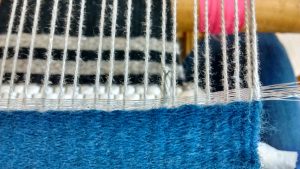
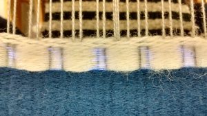
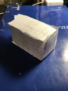
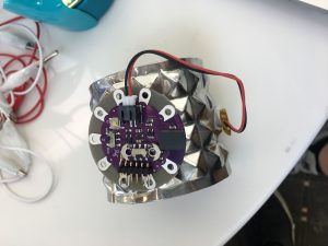
 Using a large cuff right now to have an idea of what the prototype could look like.


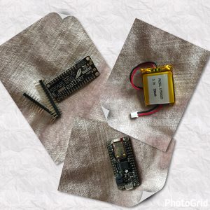
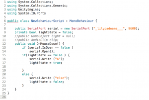
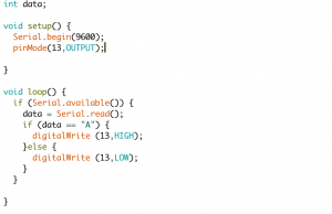
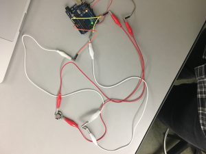
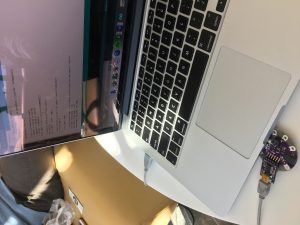
On Tuesday Keegan was able to get the Simblee up and running with code to use a vibration motor uploaded from computer to laptop. This was a step in the right direction, but the next step will be trying to upload code through Bluetooth not just through a corded connection. The Bluetooth on the Simblee was proven to work to at least his iPhone though the Simblee mobile application.

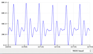
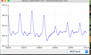
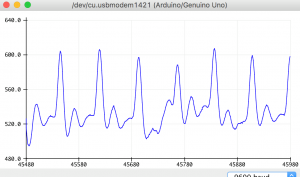
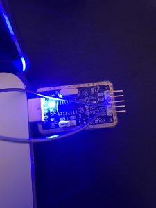
The uploaded Simblee Bluetooth code was for a temperature probe or just the internal temperature of the Simblee device. This code was fairly basic (and already completed) but it was still exciting to see the iPhone connect via Bluetooth and display a temperature value that actually responded to temperature changes.

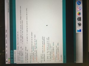
Moving forward with code we want to work on how to program via Bluetooth and work on using time in the code. I haven’t quite figured how to work in sending a signal after a certain amount of time has passed. In my head it should be a simple if== “HIGH” for 3 s…then “do this” but the code has not worked out so simply.

EoS Post 3

Progress: This post is in the wake of a minor setback, I was unable to figure out how to use the previous range finder after spending a week poking and prodding it with various settings. So I started my fallback plan and ordered another range finder off of sparkfun, this one goes up to about 6 feet which is decent for showing the application of the EoS. It should arrive Thursday so I’m hoping I’ll have it before class.

Problems: The biggest issue over the past 3 weeks was trying to decipher the cryptic range finder module I originally got. I’m receiving some sort of data from it but I could not figure out what it was/meant and it made minimal to no sense to me. I would get a value of 0 when measuring distance no matter what setting I’d use and I switched up to about every setting under the sun.


Plans: My plan for this week is to solder the arduino to the OLED screen and get that reading correct numbers. Then if I have the range finder I’d like to also solder that to the arduino and get the code written down. Lastly I will figure out my power needs and order the battery and the charger circuit, which when that all arrives I’ll be able to start creating some models of the casing I need since this new range finder is a different shape and size than the old one.

Unconventional Honesty Post 3

Hoorah! We finally got all of our project parts!
What we got in: 3 Neopixel strips, a heart rate monitor, a jacket to hack, and our lillypads!


We have begun learning about the heart rate monitor and checking that we can process the information it collects.

We have also begun hacking into the jacket by sewing the neopixel strips on and breaking into the lining.I have found difficulty with attacking the strips; I plan to look for easier ways to attach during class.

Our plan for this week: We’re going to complete our first mock up of the jacket, with attached neopixels, wiring, and functional heart rate monitor. We’re also going to look at the possible designs we can create with layers of neopixels!

Muscle jet Post#3

This past week I made a few test with the fiber optic.

1. Using only FO with a diameter of .25mm I weaved a 1.5 cm section, below you can see how it looks.

this FO is quite flexible and on the next video you can see it lights up enough to be seen in the dark after being sanded with a rough grade sand paper.

however it lacks structure, the FO slips through the warp

2.  Using FO with a diameter of .50mm alternated with a cotton strand (?)             I weaved a 1.5 cm section below you can see how it looks.

this FO is much less flexible, but the combination with the cotton gives more structure. On the down side alternating the FO hides half of it, as you can see in the video.

this one lights up more, so its pretty much a trade off between flexibility and surface area (the more surface area the more light).

Conclusions:

  1. Using a thinner cotton strand for the warp and the weft will allow the FO to show more.
  2. Instead of alternating FO and Cotton, I’l  do a double weft FO + Cottton.
  3. I will sand the FO before weaving it, its harder but gives better results.
  4. It only looks cool on the dark.


Unconventional Honesty Post 2

We have started experimenting with out Neopixel designs and fabric overlay! We have videos of several fabric overlay options, but the MB are too large to be uploaded onto the site.

We have uploaded the videos to youtube!


Our most promising overlay is a double organza, which we would style into a vest over the neopixels. The interior of the jacket will have a quilt-like stitching into it so that we can hide pockets inside without compromising the aesthetic outside. We were also able to find the neopixel coding in Arduino which with will begin playing with to find the right design we want.

Our issues still remain with not having the sensor and neopixel strips, but we are expecting both any day now.

Plan for the week: Once we get in our final pieces we will attach to our first prototype, test run it, and start to work out the kinks! Over spring break, Jade will find a suitable fashion jacket to hack and we will begin working on our second prototype.

Step by Step

  • Last week
    • Heel Components
      • The 1st version of the 3D prints for the heel component arrived. However, they did not fit in each other, so I tried modifying the physical components with a jewelry file to see if I could get them to fit. This caused the threads on the largest of the rings to snap.
    • Platform work
      • I hollowed out the pre-existing platform of a heel that I own so that it can be used in the shoe until a custom platform has been fabricated. 
  • This week
    • Heel Components
      • I will continue to modify the 3D components and order the second version of the design.
    • Bluefruit
      • I will start to experiment with the Bluefruit components to see if I can get the device to work.
  • Next week
    • Heel Components
      • If the second version of the components function properly, I will order the final version in metal. Otherwise, I will continue to iterate and order new versions.
    • Motor
      • While in Milwaukee, I will go to American Science and Surplus to see if they have recommendations on small motors for the shoe.
    • Bluefruit
      • Once I have the motor, I will begin experimenting with the Bluefruit board to see if I can get it to spin the motor in two directions.

Muscle jet-Post #2

A few bad news this past week.

tracking

In parallel I’m still working on the code:  Getting an analog input to change a color scale.


Based on this code and…..

also a light sensor code.


    /******************************************************************************

LilyPad Light Sensor Example
Angela Sheehan
SparkFun Electronics

This example code reads the input from a LilyPad Light Sensor and displays in
the Serial Monitor.

Light Sensor connections:
   * S pin to A3
   * + pin to A5
   * - to -

******************************************************************************/

// Set which pin the Signal output from the light sensor is connected to
// If using the LilyPad Development Board, change this to A6
int sensorPin = A3;
// Create a variable to hold the light reading
int lightValue;

void setup()
{
    // Set sensorPin as an INPUT
    pinMode(sensorPin, INPUT);

    // Set pin A5 to use as a power pin for the light sensor
    // If using the LilyPad Development Board, comment out these lines of code
    pinMode(A5, OUTPUT);
    digitalWrite(A5, HIGH);

    // Initialize Serial, set the baud rate to 9600 bps.
    Serial.begin(9600);
}

void loop()
{


for next week I’ll do what I had planned for this one:

  • Weaving the fiber optic
  • finishing the code

Week 2 Post – Haptic Glove

  1. An image or video 
    Tested the wires.

    Connect Unity to Arduino (Unity part) [Using touching the item in Unity to turn on and off LED as an example]
    Read data from Unity (Arduino part) [Using touching the item in Unity to turn on and off LED as an example]
  2. A Listing of accomplishments made by all group members for the previous week
    1. Received the actuator wires and tested on them
    2. Used heat tape to prevent heat from transforming to fingers
    3. Learned about how to implement wires on gloves
    4. Connected Unity to Arduino
  3. A description of problems encountered and outstanding issues
    1. We had some conflicting test results. Still not aware if the problem lay in the wire, the gauge, or the microcontroller being used. Problems may or not be that the actuator wire is not set to form currently, the result would be a lackluster performance of the wire, possibly leading to faster degradation of the wire when activated. (Maybe we burn a wire.)
    2. There is more refined technical information on how to use the Actuator wire, considering the length, gauge, and power supply that we need to sort through and apply. Currently, we are in the trial and error stage of material and component testing:
      1. -Wires need a standardized system of shaping for memory setting
      2. -Need to figure out a “tender” was to set the memory of the wire without superheating it and burning the wire.
      3. -Controller communication in relation to power output still needs to be established and regulated.
        1. Needed current: 0.2 A; Arduino voltage: 5V
        2. Calculated needed resistance: 25 ohms
        3. Wires’ resistance: 126 ohms/ meter ⇒ 1.26 ohms/centimeter
        4. So we still need 25-1.26x ohms(set x as the length of the wire) to guarantee 0.2A current
  4. A plan for the next week of work
    1. By next week we will have determined if materials need to be re-evaluated for the practicality, or usability. Reorder any parts or new parts, create an experimental prototype that will hopefully be a functioning prototype.
    2. Keep working on Unity.

Sirena 3/14/17

So far we have worked on a couple of things.

Last week Keegan was able to figure out the code for the vibration motor using Arduino.

Emma was also able to work on the design analysis of the bracelet- figuring out sizing and how the Simblee and rest of the tech can fit into the bracelet. Mapping it out is a little difficult without having the entire product assembled but we were able to get an idea of how large the bracelet will be. We found some scrap pleather to piece together but now we are currently working with some clay to get an even better idea of the design.  

Problems we have faced is working with the pleather to get an idea of the shape of the bracelet- it is still in the very beginning stages.

We also haven’t been able to connect our Simblee yet- we plan on getting a new cord hoping that will allow it to work.

Next steps include getting the Simblee to work and working with the clay for design purposes.  Also working on getting the button to work.

EoS Week 2

Progress: I was able to download some slightly questionable software from a Chinese website allowing me to find my serial port that my USB to TTL converter uses. So I stripped some wire and hooked up the transmit and receive ports on the converter to see if it would work, and my “test” did transmit and receive properly!


I then built a rough housing prototype out of simple paper and it what I didn’t even think of was how tall it was going to be. It is pretty tall for an attachment on the glasses and splitting it between the two sides won’t remedy that. It doesn’t appear to be too wide however I think splitting will ease the burden from one side to both sides of the user’s glasses.

I

Issues: Mainly the communication with the converter to the range finder is somehow not working properly and I would love to get that figured out this week so I can move on to implementing code and the OLED screen. And of course the issue of the housing should be figured out once I build another prototype housing unit that is split between both sides of the user’s glasses.

Plan For The Week: Get the range finder working, start displaying on the OLED screen and get some Arduino code put up to communicate with both of them. Also build the other housing prototype to see the difference between the two.